Determine Manufacture Date
Part Description | XTS | XTS | XTS | XTS3 |
08/1999 to 05/2003 | 06/2003 to 04/2005 | 05/2005 to 04/2008 | 07/2007 to 07/2012 | |
Inducer Fan Blower | TP-55A | TP-55A | TP-55A | TP-55A |
Circuit Board | TP-351A & TP-390* | TP-351A | TP-351A | TP-351A |
Flame Rod | TP-222 | TP-222 | TP-222 | TP-222 |
Ignition Device | TP-50A | TP-50A | TP-50A | TP-50A |
Gas Valve (Nat) | TP-240 | TP-240 | TP-240 | TP-3040 |
Gas Valve (LP) | TP-241 | TP-241 | TP-241 | TP-3041 |
Control Voltage | 120V | 120V | 120V | 120V |
IOM Link |
Pressure Switch
Model | Year Range | 50 MBH | 60-75 MBH | 100 MBH | 125 MBH | 150 MBH | 175 MBH | 200 MBH |
XTS | 08/1999 to 05/2003 | TP-264B | TP-264B | TP-264B | TP-264D | TP-264D | TP-264D | |
XTS | 06/2003 to 04/2005 05/2005 to 04/2008 | TP-264B | TP-264B | TP-264B | TP-264E | TP-264E | TP-264D | TP-264F |
XTS3 | 07/2007 to 07/2012 | TP-264E | TP-264D | TP-1264A | TP-1264A | TP-264F | TP-264F | TP-264F |
Burner Control Box Parts
Other Common Parts
Tube and Reflector Components
| Reflector End Cap Clip - (8) pcs. | $2.00 Max: 49 Min: 1 Step: 1 Add to cart | |
| Reflector Center Support | $15.00 Max: 9 Min: 1 Step: 1 Add to cart | |
| 4" Wire Hanger with Spring. | $16.50 Max: 9 Min: 1 Step: 1 Add to cart | |
| 36 in. Interlocking Turbulator Baffle Section | $17.00 Max: 19 Min: 1 Step: 1 Add to cart | |
| Reflector End Cap. 2 pcs (includes attachment clips) | $19.00 Max: 17 Min: 1 Step: 1 Add to cart | |
| 4" Tube Clamp | $25.00 Max: 1 Min: 1 Step: 1 Add to cart | |
| 4" Stainless Steel Tube Clamp. (1) clamp needed on 150-200 MBH systems. | $36.00 Max: 6 Min: 1 Step: 1 Add to cart | |
| Reflector Elbow - 90° bend, with polished, one side bright reflector elbow. | $75.00 Max: 5 Min: 1 Step: 1 Add to cart | |
| Elbow - 6” radius, 90° bend, 4” diameter | $95.00 Max: Min: 0 Step: 1 Add to cart | |
| Refelctor "U" to cover a TF1B "U" fitting. | $100.00 Max: 15 Min: 1 Step: 1 Add to cart |
Hanging Hardware
| Five foot chain set with two (2) “S” hooks. | $7.00 Max: 34 Min: 1 Step: 1 Add to cart | |
| Reflector Angle Mounting Bracket - "Brass Knuckle" | $9.00 Max: 12 Min: 1 Step: 1 Add to cart | |
| Single Mount Bracket - for U tube configuration
| $28.00 Max: 20 Min: 1 Step: 1 Add to cart |
Air Intake
Guidelines | Outside Air | |||
see General Manual for complete requirements Combustion Air Requirements Combustion air may be supplied to the heater by indoor or outdoor means. If using combustion air intake from indoors, the required volume of the space must be a minimum of 50 ft3 per 1,000 BTU/h unless the building is of unusually tight construction. Non-contaminated outside air for combustion must be ducted to the heater if any of the following apply: • Chemicals such as chlorinated or fluorinated hydrocarbons (typical sources are refrigerants, solvents, adhesives, degreasers, paints, paint removers, lubricants, pesticides, etc.). • High humidity. • Contaminants such as sawdust, welding smoke, etc. • Negative building pressure. • Unusually tight construction where there is an air infiltration rate of less the 0.40 air changes per hour. | ||||
| Wall inlet cap, 4” O.D. with bird screen. For use with outside air option. Bird screen ensures open air flow to unit. Used for 0-20’ of 4” intake. Used on all low intensity tube heaters | $37.00 Max: 13 Min: 1 Step: 1 Add to cart | |
| 4" Flexible Air Inlet Hose Used on all low intensity tube heaters 4" flexible air inlet rubber hose (black) with DWV adapter affixed to AIRH. Mates to 4" DWV pipe. Replaces AIB 18" in length.
| $51.00 Max: 10 Min: 1 Step: 1 Add to cart | |
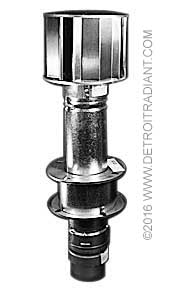
| 4" Rooftop Vent Package. Can also be used for Air Intake. | $210.00 Max: 25 Min: 1 Step: 1 Add to cart |
Venting
Rooftop | Sidewall | Common Rooftop | Common Sidewall | Unvented |
General Venting Requirements The venting system for the heating system may terminate horizontally through a sidewall or vertically through the roof, and may be individually or commonly vented. Configuration of the vent termination determines the category type | ||||
Important Model Requirements: see General Manual for compete requirements | ||||
• Do not exceed a maximum vent length of 20 ft. with two elbows, 25 ft. with one elbow, or 30 ft. with no elbows. • Maintain a minimum vent length of 3 feet. • Maintain a minimum of 12 inches of straight pipe from the flue outlet before any directional changes are made in the venting system. • The equivalent length for a 4 inch 90° elbow is 5 feet. • Avoid using more than two 90° directional changes in the venting system | ||||
| Galvanized Steel Vent Outlet Cap Used on all low intensity tube heaters except LS, LD or DBS 4" O.D. with flapper. Flapper ensures proper static pressure for proper unit operation. Must be used with unvented units.
| $36.00 Max: 3 Min: 1 Step: 1 Add to cart | |
| 4" Simpson Duravent Rooftop Vent Cap
| $38.00 Max: 4 Min: 1 Step: 1 Add to cart | |
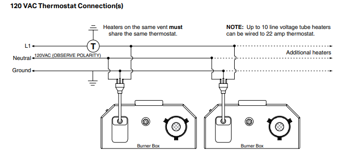
| Dual Exhaust Assembly "Y" shaped, 26 gauge galvanized steel with baffle. 4" O.D. X 4" O.D. For use when common venting (2) units. Heaters MUST share a common thermostat. Dimensions: 14" left to right (w) x 13" height. | $102.00 Max: 20 Min: 1 Step: 1 Add to cart | |
| 4" Duravent Sidewall Vent Kit (Alt. Part# 2C448) Used on all low intensity tube heaters except LS, LS3, LD3 & DBS Includes all items for sidewall venting: SWD-4, WT-4, 18BV-4, & DHC-4. Single wall vent pipe material is included. 29" long when fully assembled. NOT APPROVED FOR V2 200 MBTU/H | $184.00 Max: 24 Min: 1 Step: 1 Add to cart | |
| 4" Rooftop Vent Package. Can also be used for Air Intake. | $210.00 Max: 25 Min: 1 Step: 1 Add to cart | |
| 6" Duravent Sidewall Vent Kit Al items for sidewall venting including: SWD-4, WT-6, 18BV-6 and DHC-6. No vent pipe material is included. 30" long when fully assembled. Used on: all low intensity tube heaters | $234.00 Max: 5 Min: 1 Step: 1 Add to cart | |
| 6" Rooftop Vent Package.
| $240.00 Max: 15 Min: 1 Step: 1 Add to cart |
Controls 120V
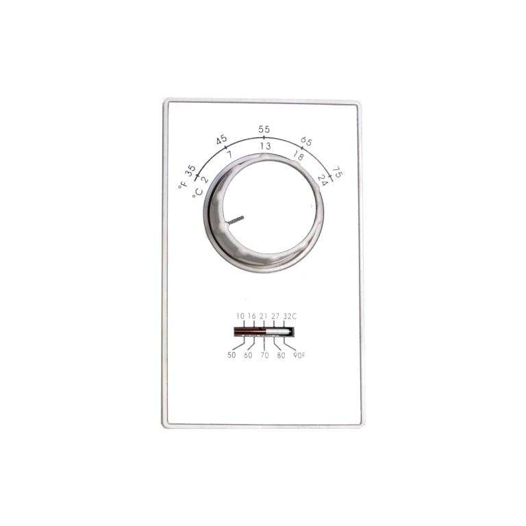
| Single stage thermostat. 35°–75°F range. 24-277 VAC | $69.00 Max: 25 Min: 1 Step: 1 Add to cart | |
| Single stage thermostat with rain tight enclosure 40°–100°F range. Can be used with 24–277 VAC. | $110.00 Max: 10 Min: 1 Step: 1 Add to cart | |
| Single stage 120 V line voltage thermostat. (4-period) programmable. 40°–86°F range | $173.00 Max: Min: 0 Step: 1 Add to cart |
Optional 24V Controls
Control 120V Heater with 24V Controls
| Combination relay transformer - For controlling 120 V units with 24 V thermostats | $120.00 Max: 2 Min: 1 Step: 1 Add to cart |
Other Information
Clearance to Combustibles
Clearance to Combustibles is defined as the minimum distance that must exist between the tube
surface, or reflector, and any combustible items (see Figure 1.1). It also pertains to the distance that
must be maintained from moving objects around the tube heater. When installing the tube heater system,
clearances to combustibles for the model tube heater and configuration must be maintained. Refer to Chart 1.1
to determine the required distances for your model.
Gas Requirements
Gas Supply
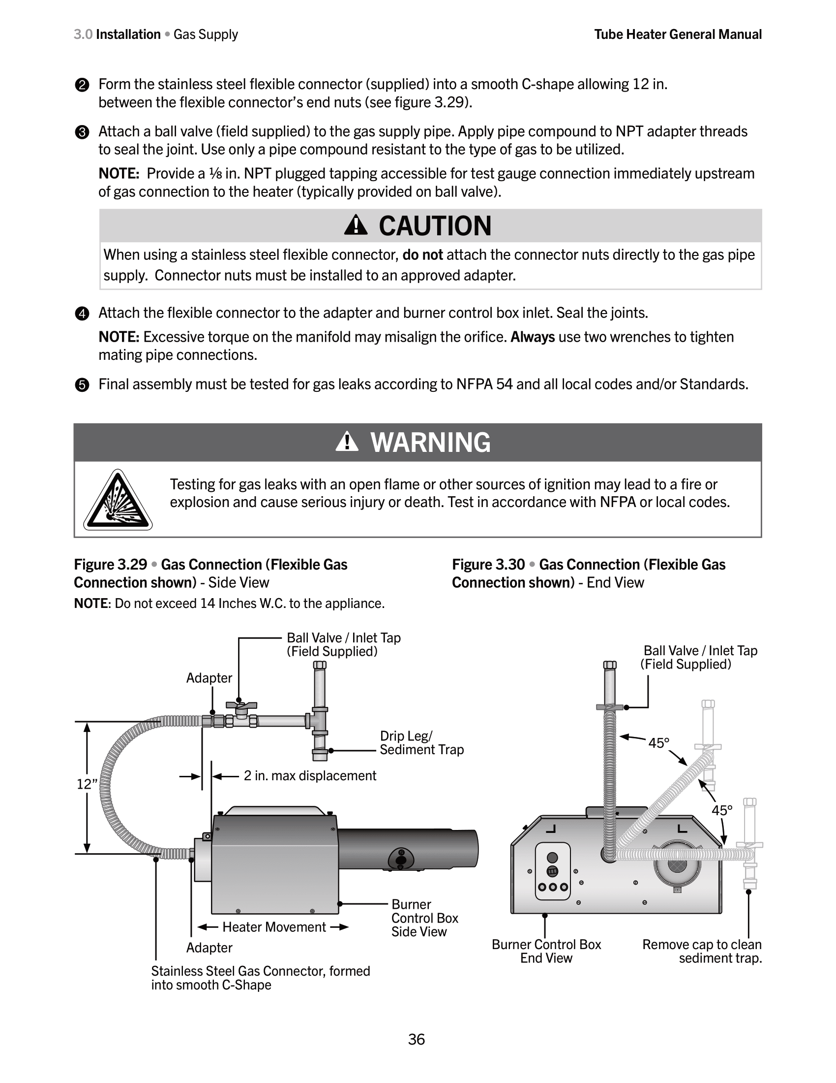
Important! Before connecting the gas supply to the burner control box:
• Verify that the heater’s gas type (as listed on the rating plate) matches that of your application.
• Check that the gas piping and service has the capacity to handle the total gas consumption of all heaters
being installed, as well as any other gas appliances being connected to the supply line.
• Check that the main gas supply line is of proper diameter to supply the required fuel pressures.
• If utilizing used pipe, verify that its condition is clean and comparable to a new pipe. Test all gas supply
lines in accordance with local codes.
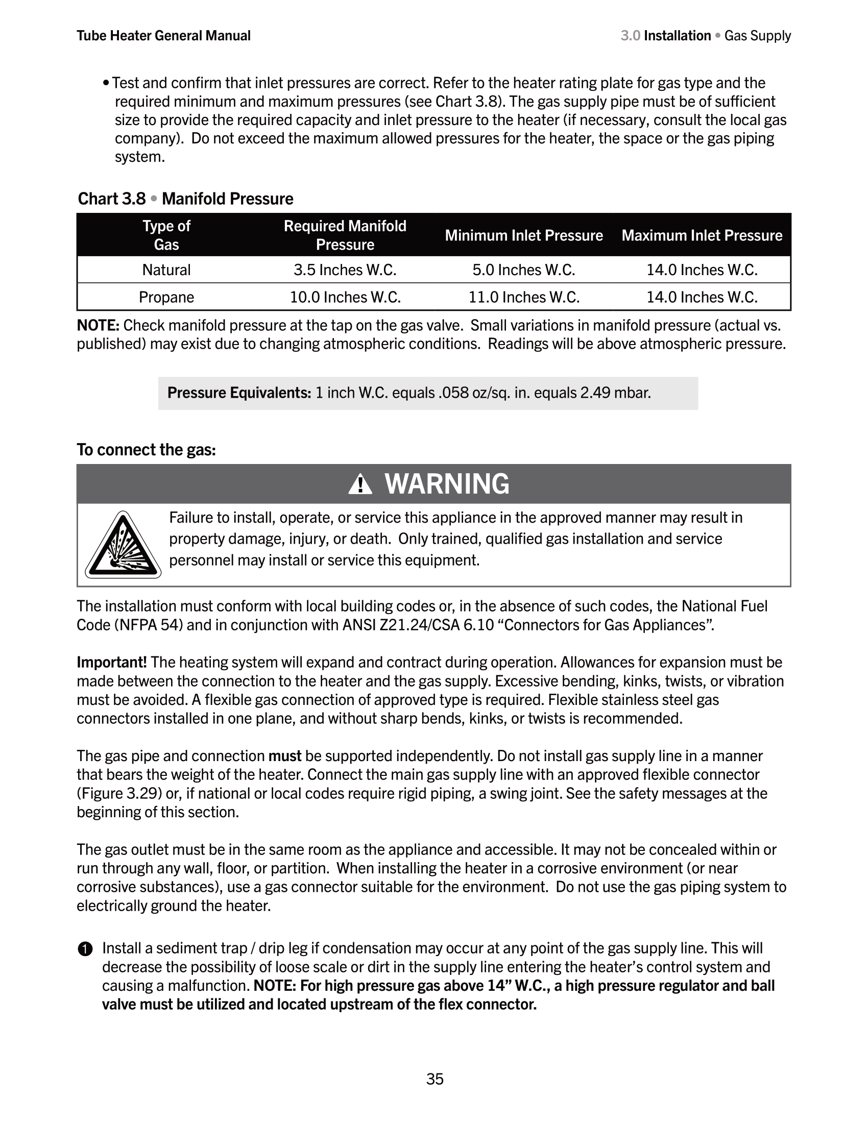
•Test and confirm that inlet pressures are correct. Refer to the heater rating plate for gas type and the
required minimum and maximum pressures (see Chart 3.8). The gas supply pipe must be of sufficient
size to provide the required capacity and inlet pressure to the heater (if necessary, consult the local gas
company). Do not exceed the maximum allowed pressures for the heater, the space or the gas piping
system.
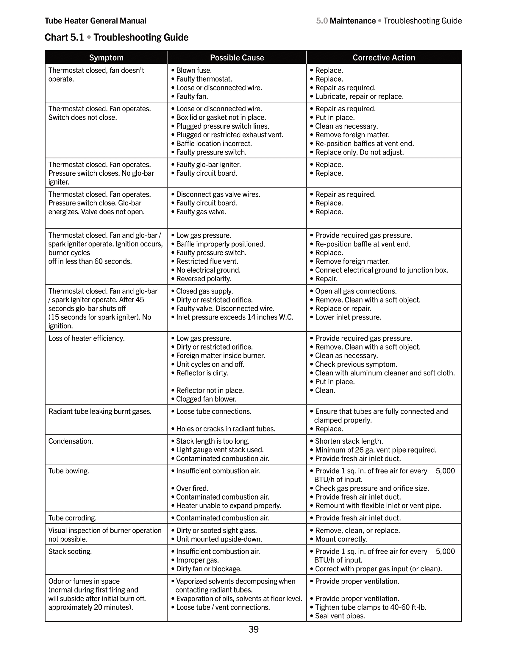
Troubleshooting
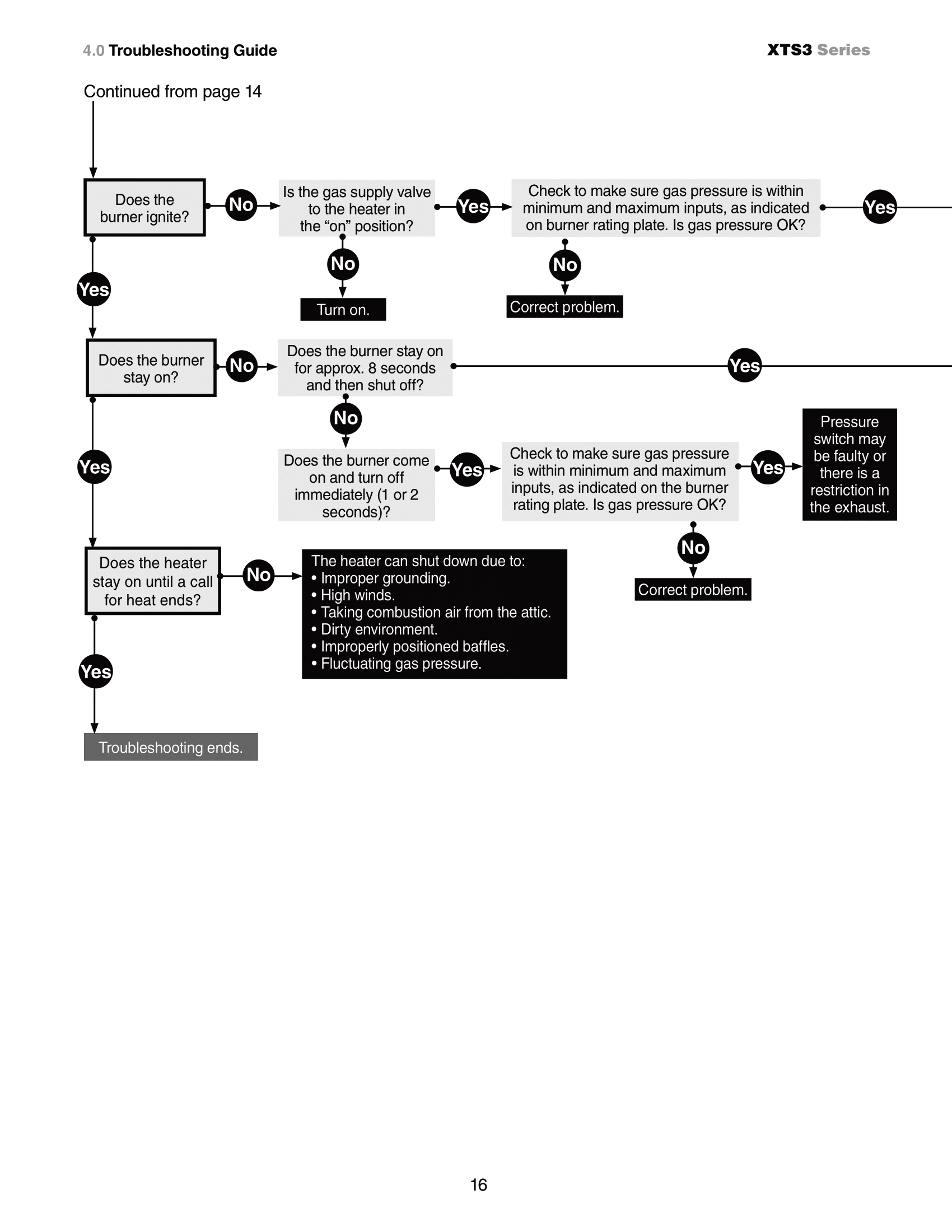
Troubleshooting XTS3 07/2007 to 07/2012
Troubleshooting XTS 08/1999 to 05/2003
Copy the following code to Gemini or other AI Agent to start a troubleshooting chat session.
Act as an expert systems troubleshooter. I am going to give you a Mermaid.js flowchart that represents our system's architecture/workflow. Your goal is to help me diagnose an issue by stepping through this flowchart with me interactively, one node at a time.
%% Troubleshooting Flowchart for XTS
%% Manufacturing date range 08/1999 to 05/2003
%% Source: xts_manual0500.pdf
%% Pages: 8-9
graph LR
%% Page 1: Initial Troubleshooting & Fan/Ignitor Checks
Start([Turn up Thermostat]) --> Q1{Does the fan
blower turn on?}
%% Fan blower NO branch
Q1 -- NO --> Q2{Is the power at the
heater 120V?}
Q2 -- NO --> A1[Find the source of the
electrical problem.]
Q2 -- YES --> Q3{Is the blower
obstructed?}
Q3 -- YES --> A2[Remove obstruction
& lubricate fan.]
Q3 -- NO --> Q4{Is there 120V
coming to the fan?}
Q4 -- NO --> A3[Correct wiring.]
Q4 -- YES --> A4[The fan is faulty and
must be replaced.]
%% Fan blower YES branch -> Ignitor checks
Q1 -- YES --> Q5{Does the ignitor
warm up and glow red?}
Q5 -- NO --> Q6{Is the ignitor
physically damaged?}
Q6 -- YES --> A5[Replace ignitor.]
Q6 -- NO --> Q7{Check voltage at ignitor during ignition
sequence 30-45s after power.
Is it 120V?}
Q7 -- YES --> Q8{Is the resistance through
the ignitor 45-400Ω?}
Q8 -- NO --> A5
Q7 -- NO --> Q9{Is the inlet or outlet of the unit
obstructed? e.g., ice, birds nest, dirt}
Q9 -- YES --> A6[Remove obstruction.]
Q9 -- NO --> Q10{Check for loose wiring/restrictions in
hose connections to pressure switch.
Are they ok?}
Q10 -- NO --> A7[Repair wiring or hose
connections.]
Q10 -- YES --> Q11{Safety pressure switches: Temporarily place
jumpers across terminals of each switch,
one at a time with cover reinstalled.
Does ignitor glow red?}
Q11 -- YES --> A8[Replace appropriate switch after verifying:
- Baffles are in farthest tubes
- Heater/blower/intake/exhaust are clean
- 4in intake pipe is <= 20ft and/or 2 elbows
- No negative pressure at air intake]
Q11 -- NO --> Q12{Temporarily place jumpers across both pressure
switches and check for 120V going from
switch to circuit board. Is there 120V
entering the circuit board?}
Q12 -- NO --> A9[Faulty wiring. Repair or
replace wiring.]
Q12 -- YES --> A10[Replace circuit board.]
%% Page 2: Gas Valve & Burner Operation
Q5 -- YES --> Q13{After ignitor is warmed up,
does gas valve open?}
%% Gas Valve NO branch
Q13 -- NO --> Q14{Test for 120V at valve during valve opening
period 30-45s after power to heater.
Is there 120V to valve?}
Q14 -- NO --> A11[Possibly, the circuit board and/or
wiring harness is faulty. Replace them.]
Q14 -- YES --> Q15{Check gas pressure within min/max inputs
on AGA burner rating label.
Is gas pressure OK?}
Q15 -- NO --> A12[Correct problem.]
Q15 -- YES --> A13[Replace gas valve.]
%% Gas Valve YES branch -> Burner lighting
Q13 -- YES --> Q16{Does the burner light?}
Q16 -- NO --> Q17{Is the gas cock in
an ON position?}
Q17 -- NO --> A14[Correct problem.]
Q17 -- YES --> Q18{Check gas pressure within min/max inputs
on AGA burner rating label.
Is gas pressure OK?}
Q18 -- NO --> A15[Correct problem.]
Q18 -- YES --> A16[Make sure gas lines
were purged of air.]
%% Burner Stay On Checks
Q16 -- YES --> Q19{Does the burner
stay on?}
%% Burner stays on -> Final operation
Q19 -- YES --> Q20{Does heater stay on
until call for heat ends?}
Q20 -- YES --> End([Troubleshooting ends.])
Q20 -- NO --> Box1[The following can cause the heater to shut down:
- Improper grounding
- High winds
- Taking combustion air from the attic
- Dirty environment
- Baffle not located properly
- Fluctuating gas pressure]
%% Burner does NOT stay on -> Diagnostics
Q19 -- NO --> Q21{Does the burner stay on for
approx. 8 seconds and then shut off?}
%% Stays on 8 seconds
Q21 -- YES --> Q22{Is the heater properly grounded?
Is the heater's polarity correct?}
Q22 -- NO --> A17[Correct problem.]
Q22 -- YES --> Q23{With voltmeter, check DC voltage at flame rod.
Is it greater than 30 Volts DC?}
Q23 -- YES --> A18[Check to make sure flame sensor wire is
OK and then replace circuit board.]
Q23 -- NO --> A19[Sensing rod is faulty or flame is weak.
Check heater operating gas pressure on AGA label
and replace sensing rod if needed.]
%% Shuts off immediately (1-2 seconds)
Q21 -- NO --> Q24{Does the burner come on and then
turn off immediately 1 or 2 seconds?}
Q24 -- YES --> Q25{Check pressure within min/max inputs
on AGA burner rating label.
Is gas pressure OK?}
Q25 -- NO --> A20[Correct problem.]
Q25 -- YES --> A21[Exhaust pressure switch may be
faulty or there is a restriction in the exhaust.]
%% Style Definitions
classDef startEnd fill:#d4ebf2,stroke:#333,stroke-width:2px,color:#000;
classDef decision fill:#fff2cc,stroke:#d6b656,stroke-width:2px,color:#000;
classDef action fill:#d5e8d4,stroke:#82b366,stroke-width:1px,color:#000;
classDef fault fill:#f8cecc,stroke:#b85450,stroke-width:1px,color:#000;
classDef info fill:#e1d5e7,stroke:#9673a6,stroke-width:1px,color:#000;
%% Apply Classes
class Start,End startEnd;
class Q1,Q2,Q3,Q4,Q5,Q6,Q7,Q8,Q9,Q10,Q11,Q12,Q13,Q14,Q15,Q16,Q17,Q18,Q19,Q20,Q21,Q22,Q23,Q24,Q25 decision;
class A1,A2,A3,A6,A7,A12,A14,A15,A16,A17,A20 action;
class A4,A5,A8,A9,A10,A11,A13,A18,A19,A21 fault;
class Box1 info;