DX Common Parts


-

TP-851B
$230.00 -
TP-828A
$10.00 -

TP-826
$43.00 -

TP-78D
$190.00 -

TP-55A
$200.00 -

TP-50A Glo-Bar Hot Surface Igniter
$59.00 -

TP-390
$22.00 -

TP-351A
$195.00 -
TP-328
$11.00 -

TP-3215
$285.00 -

TP-3041
$180.00 -

TP-3040
$180.00 -

TP-264F
$59.00 -

TP-264E
$59.00 -

TP-264D
$59.00 -

TP-264C
$59.00 -

TP-264B
$59.00 -

TP-260G
$59.00 -

TP-260F
$59.00 -

TP-241
$181.00 -

TP-240
$181.00 -

TP-222
$25.00 -
TP-1428A
$10.00 -

TP-1264A
$59.00 -

TP-1040
$195.00
Tube and Reflector Components

 | Reflector End Cap Clip - (8) pcs. | |
 | Reflector Center Support | |
 | 4" Wire Hanger with Spring. | |
 | 36 in. Interlocking Turbulator Baffle Section | |
 | Reflector End Cap. 2 pcs (includes attachment clips) | |
 | 4" Tube Clamp | |
 | 4" Stainless Steel Tube Clamp. (1) clamp needed on 150-200 MBH systems. | |
 | Reflector Elbow - 90° bend, with polished, one side bright reflector elbow. | |
 | Elbow - 6” radius, 90° bend, 4” diameter | |
 | Refelctor "U" to cover a TF1B "U" fitting. |
Hanging Hardware


Air Intake
Guidelines | Outside Air | |||
Combustion Air Requirements Combustion air may be supplied to the heater by indoor or outdoor means. If using combustion air intake from indoors, the required volume of the space must be a minimum of 50 ft3 per 1,000 BTU/h unless the building is of unusually tight construction. Non-contaminated outside air for combustion must be ducted to the heater if any of the following apply: • Chemicals such as chlorinated or fluorinated hydrocarbons (typical sources are refrigerants, solvents, adhesives, degreasers, paints, paint removers, lubricants, pesticides, etc.). • High humidity. • Contaminants such as sawdust, welding smoke, etc. • Negative building pressure. • Unusually tight construction where there is an air infiltration rate of less the 0.40 air changes per hour. | ||||
 | Wall inlet cap, 4” O.D. with bird screen. For use with outside air option. Bird screen ensures open air flow to unit. Used for 0-20’ of 4” intake. Used on all low intensity tube heaters | |
 | 4" Flexible Air Inlet Hose Used on all low intensity tube heaters 4" flexible air inlet rubber hose (black) with DWV adapter affixed to AIRH. Mates to 4" DWV pipe. Replaces AIB 18" in length.
| |
 | 4" Rooftop Vent Package. Can also be used for Air Intake. |
Venting
Rooftop | Sidewall | Common Rooftop | Common Sidewall | Unvented |
General Venting Requirements The venting system for the heating system may terminate horizontally through a sidewall or vertically through the roof, and may be individually or commonly vented. Configuration of the vent termination determines the category type | ||||
Important Model Requirements: | ||||
• Do not exceed a maximum vent length of 20 ft. with two elbows, 25 ft. with one elbow, or 30 ft. with no elbows. • Maintain a minimum vent length of 3 feet. • Maintain a minimum of 12 inches of straight pipe from the flue outlet before any directional changes are made in the venting system. • The equivalent length for a 4 inch 90° elbow is 5 feet. • Avoid using more than two 90° directional changes in the venting system | ||||
 | Galvanized Steel Vent Outlet Cap Used on all low intensity tube heaters except LS, LD or DBS 4" O.D. with flapper. Flapper ensures proper static pressure for proper unit operation. Must be used with unvented units.
| |
 | 4" Simpson Duravent Rooftop Vent Cap
| |
 | Dual Exhaust Assembly "Y" shaped, 26 gauge galvanized steel with baffle. 4" O.D. X 4" O.D. For use when common venting (2) units. Heaters MUST share a common thermostat. Dimensions: 14" left to right (w) x 13" height. | |
 | 4" Duravent Sidewall Vent Kit (Alt. Part# 2C448) Used on all low intensity tube heaters except LS, LS3, LD3 & DBS Includes all items for sidewall venting: SWD-4, WT-4, 18BV-4, & DHC-4. Single wall vent pipe material is included. 29" long when fully assembled. NOT APPROVED FOR V2 200 MBTU/H | |
| | 4" Rooftop Vent Package. Can also be used for Air Intake. | |
 | 6" Duravent Sidewall Vent Kit Al items for sidewall venting including: SWD-4, WT-6, 18BV-6 and DHC-6. No vent pipe material is included. 30" long when fully assembled. Used on: all low intensity tube heaters | |
| | 6" Rooftop Vent Package.
|
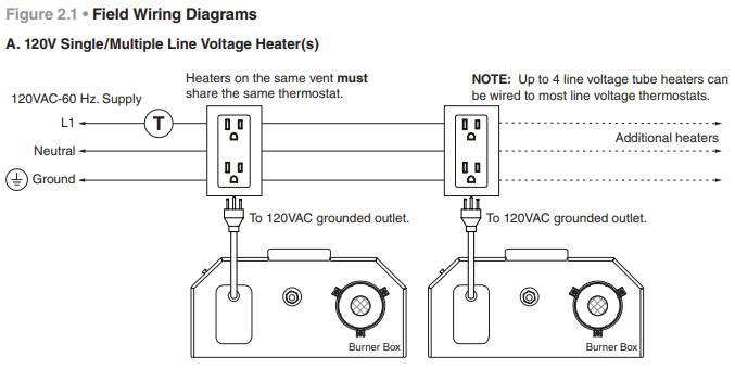
Controls 120V

Optional 24V Controls
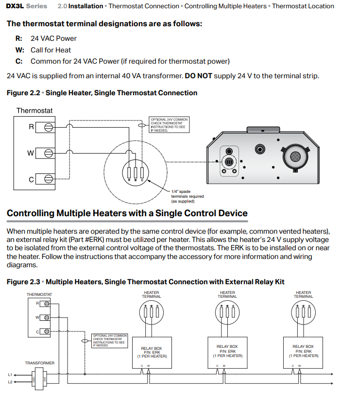
 | 40 VA transformer, 120–24 VAC primary and secondary. Used with ERK to control multiple heaters. | |
 | External Relay Kit for controlling multiple heaters with 24V control. | |
 | 24V Wall Control Switch - DX3L and similar 24V Single Stage heaters. | |
 | Single stage thermostat. 35°–75°F range. 24-277 VAC | |
 | 24V Wall 4 Hour Timer Switch - DX3L and similar 24V Single Stage heaters. | |
 | Single stage thermostat with rain tight enclosure 40°–100°F range. Can be used with 24–277 VAC. | |
 | Single stage or two stage programmable thermostat. 45°–90°F range. 24 VAC |
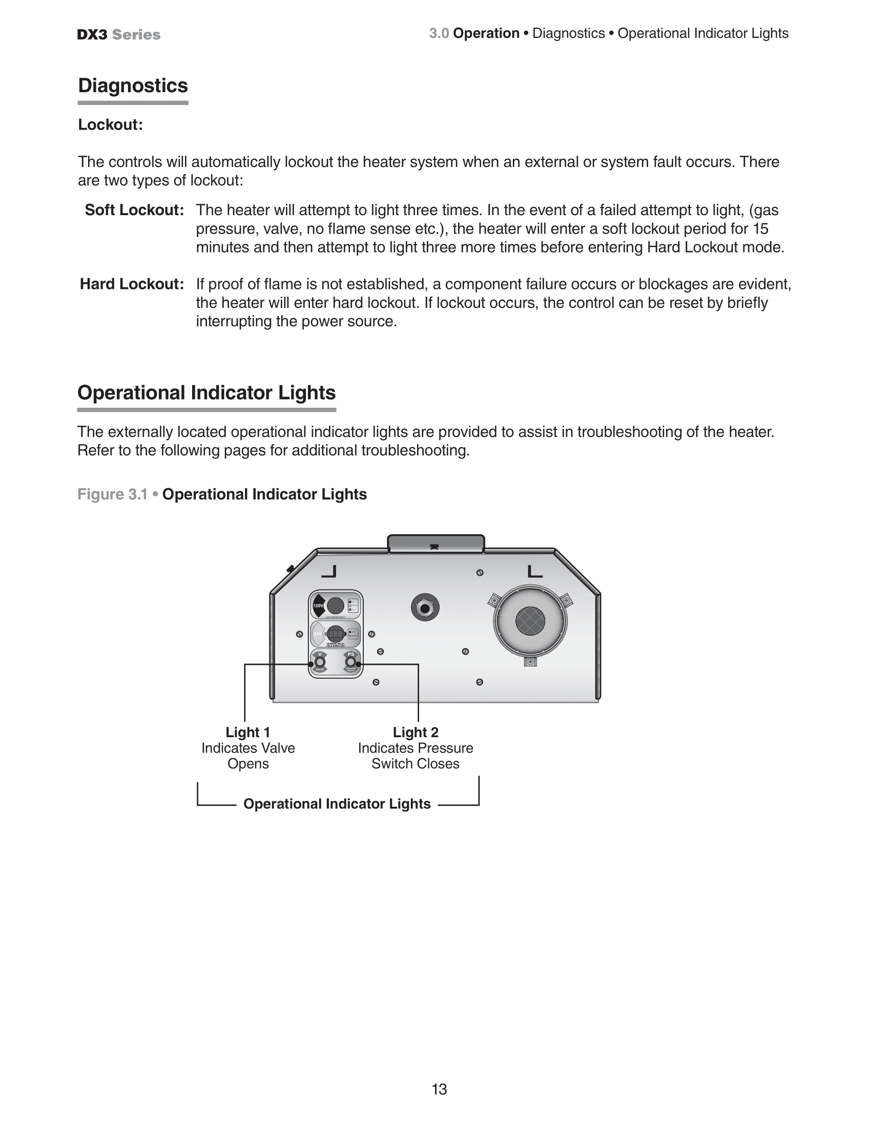
DX3 Troubleshooting
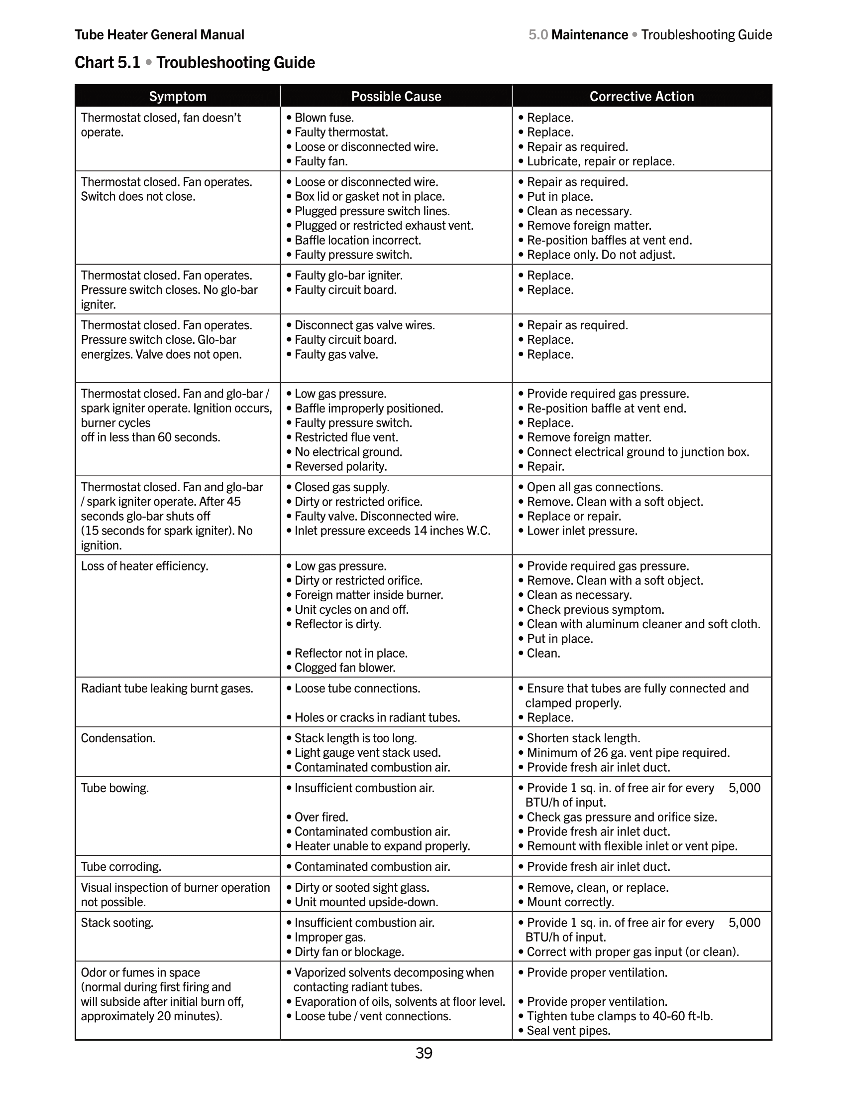
Section 1 | Section 2 |
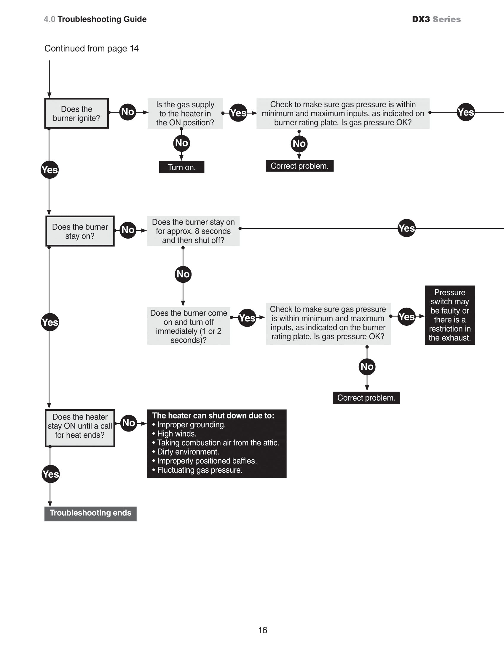 Section 3 | 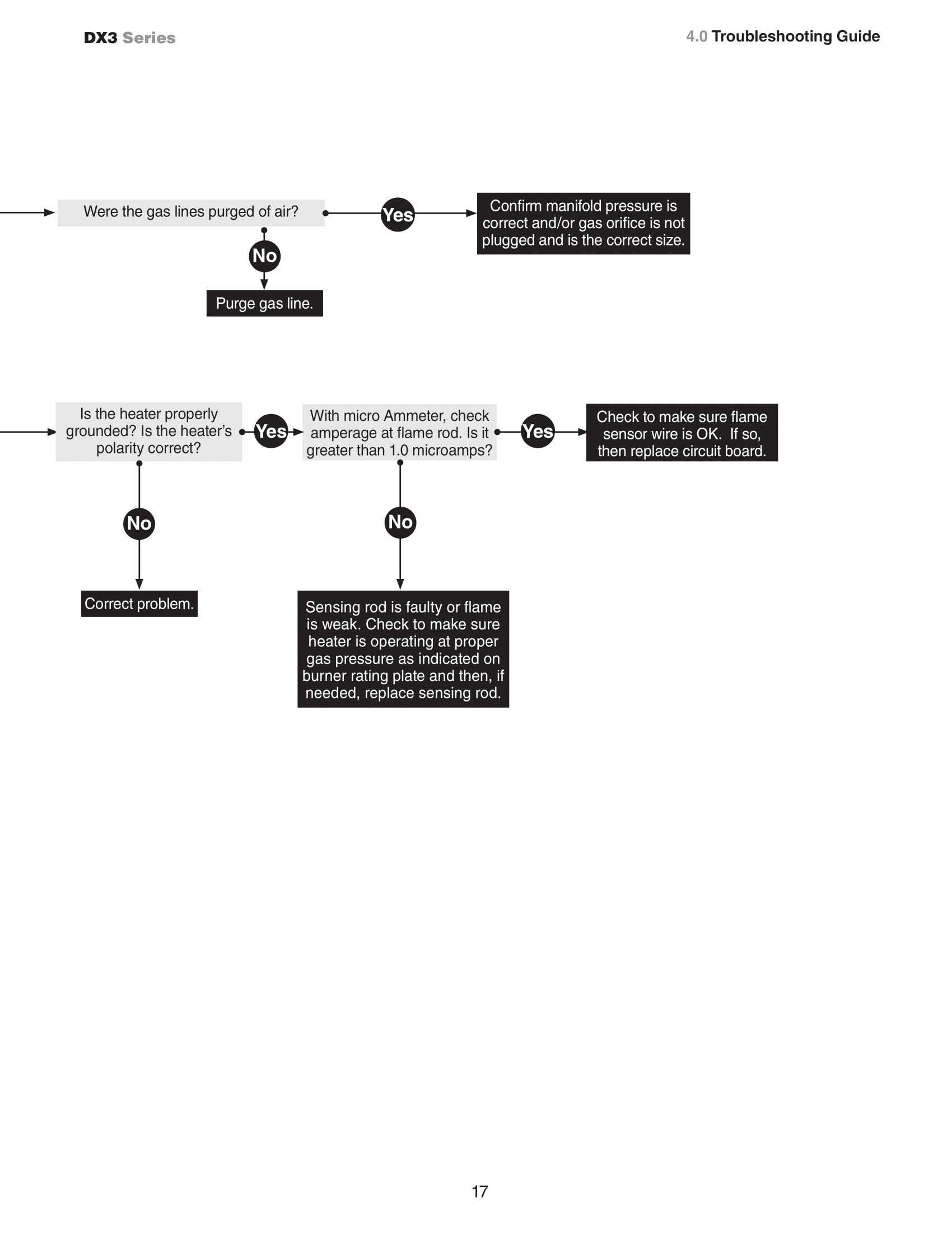 Section 4 |
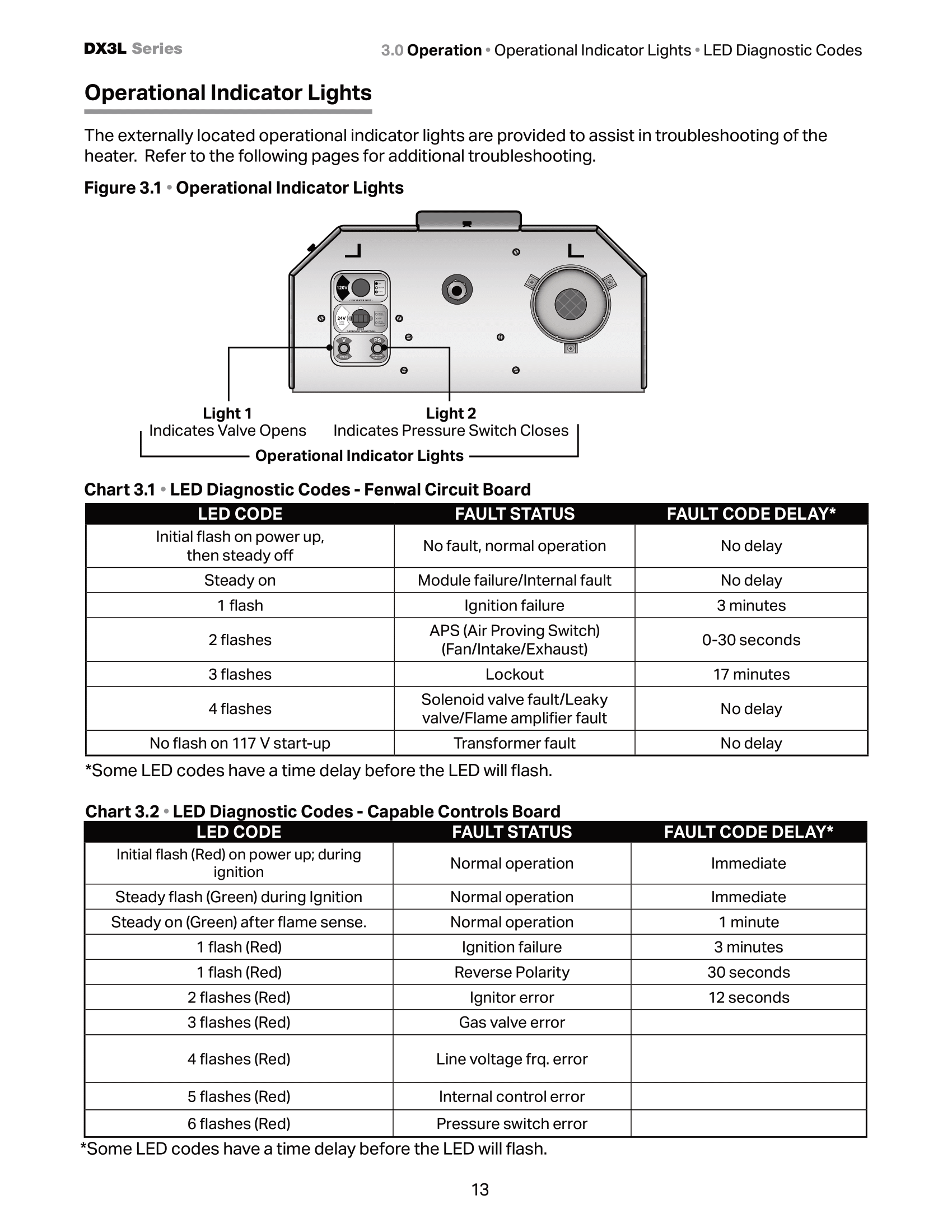
DX3L 24V Troubleshooting
Section 1 | Section 2 |
Section 3 | Section 4 |
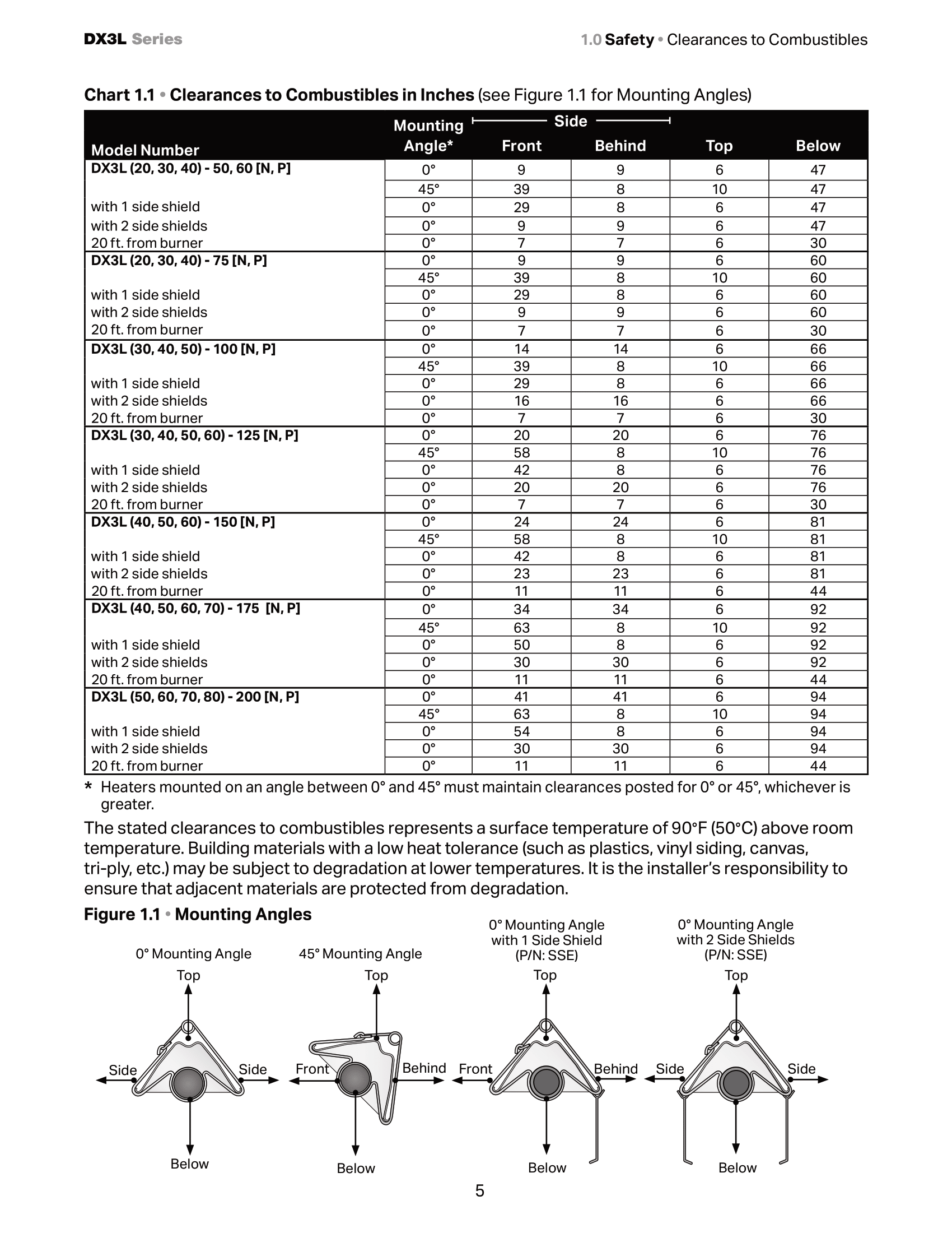
Clearances to Combustibles
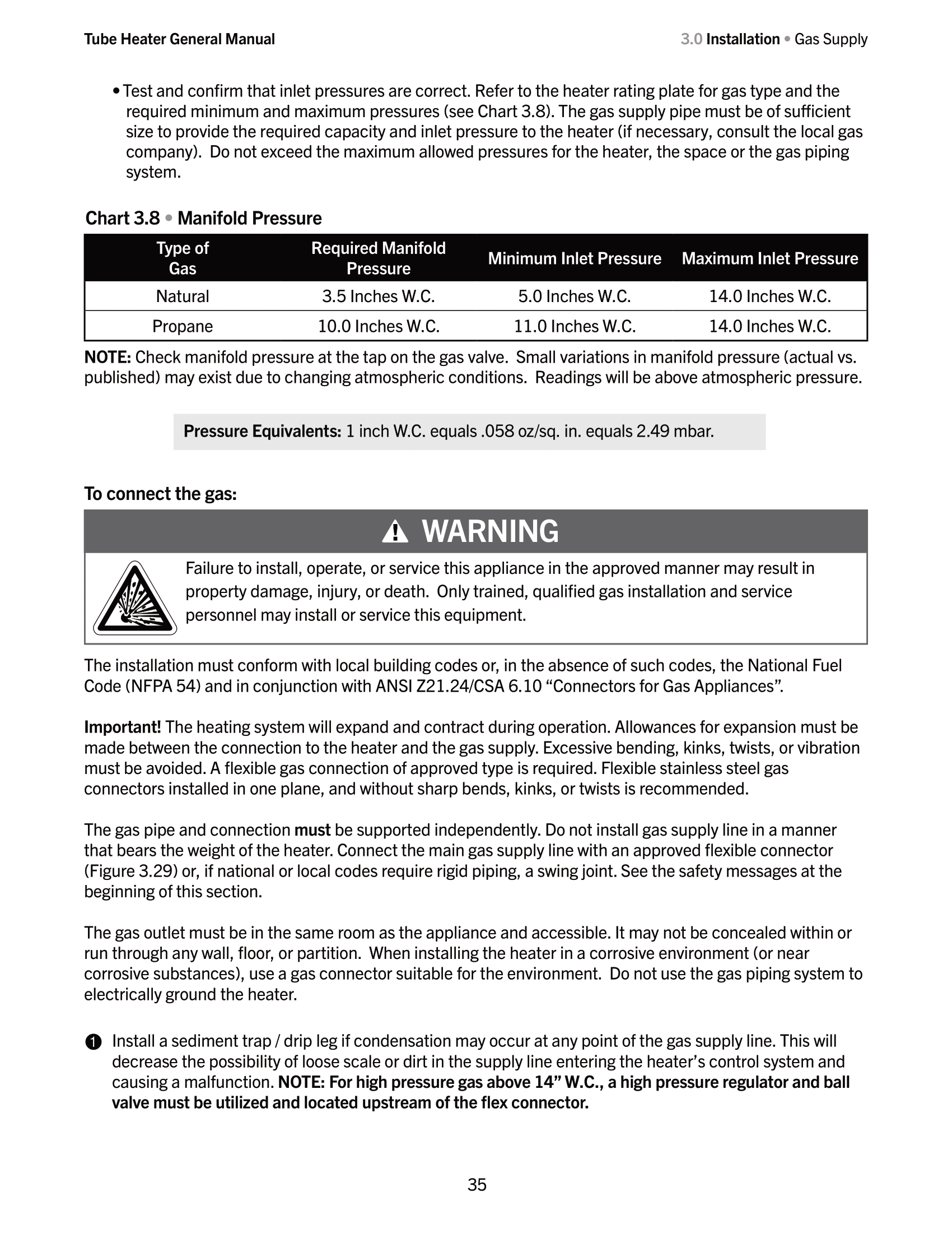
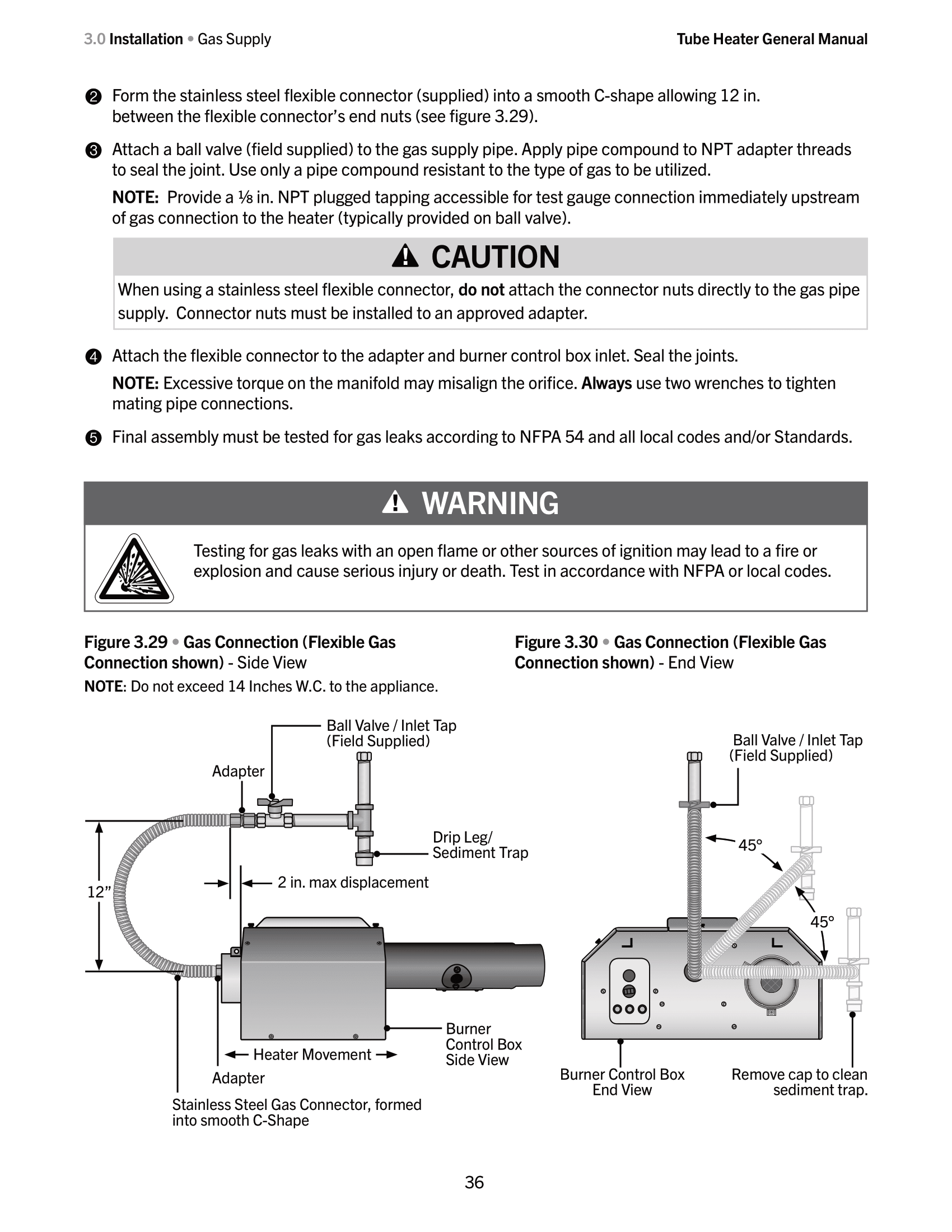
Gas Requirements